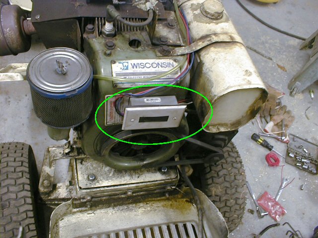
Homebuilt Solid State Ignition Module, housed in electrical box
Most of us think of complicated electronics, computer modules and such,
when the subject of ignition systems arises. Even I’ll admit that the
electronic engine control systems on today’s cars are a bit beyond my
patience to understand. But now, could the fixed advance spark timing
on a single-cylinder small engine be really that bad? Well, I’ve had a chance to find out. The official results are in. Small
engine ignition is simple. Below is a ‘case study’ of a conversion of a
12 horsepower lawn tractor engine to solid state, hall effect sensor
based, transistorized battery ignition. The picture shows the homebuilt
module in place, housed in an electrical box with aluminum cover plate.
The black strip is simply a piece of electrical tape to cover some
mounting holes.
This device is about 5/16″ square, measuring the white substrate (not
counting the leads). For those of you asking, “What in creation is a
hall effect sensor?”, it is a device that detects a strong magnetic
field in close proximity to it. It is based ot the principle that a
magnetic field can divert the flow of electricity flowing through a
conductor (the ‘hall’), causing it to flow toward the field and out of
the conductor at a different place. This is sort of like when you were
a kid, running down the hall, and suddenly you got diverted and marched
off to the principal’s office, not exactly the ‘path of least
resistance.’ (Some of you may not be able to identify this experience
like I can. <grin>)All humor aside, the hall effect sensor functions (in this application)
as a signal to turn the ignition system’s transistor ON at the
beginning of the dwell, and OFF at the precise instant at the end of
the dwell, when the charge that has built up in the coil should then
discharge with a burst of purplish-blue fire at the spark plug.
But where does the strong magnetic field come from? The original
magnets in the flywheel, of course. The spacing of the magnets that
charged the original magneto coil ignition is just right. I say it
‘very suspiciously’ resembles what the dwell should be, to properly
charge the ignition coil.
 Hall effect sensor
I haven’t gotten a schematic drawn up yet. My usual method in coming up
with designs such as these involves a bit of trial and error with a
variety of components, some 18 guage wire, and a breadboarding socket.As you can see, my workbench is a bit messy. Starting on the left, we have the 12v battery out of my Monster Quartz Halogen Bike Light.
Then we have a circular green object, with some wires coming out of it.
This part was actually not used, but is worthy of mention. It is a
timing module out of a computer hard drive. There are four hall effect
sensors on it, and I considered using them, but I ended up using some
out of an old computer keyboard instead.
Then there are three large TO208X style transistors from a switching
power supply. I was not able to use these because of their drive
requirements. I suspect they may have been IGBT’s, needing a
considerable spike on their gate leads to turn them on.
On the breadboard, the square outlined in green is the circuit under
test. The transistor is an audio amp transistor, of type 2N6578. It is
a darlington transistor, with very high gain. This means the tiny hall
effect sensor alone is capable of turning it on and off very well. Next
picture shows a closeup.
On the right hand side of the photo, you can see the original coil from
the magneto system that the engine had originally. (Note, the coil is
not connected at this particular instant.) And practically bottom
center are two magnets stuck together, which I used to test the working
of the hall effect sensor.
By simply passing the magnets by the hall effect sensor, the transistor
was turned on, charge built up in the ignition coil, and a 20kv-plus
spark was produced. I was able to draw sparks about 3/8″ long with this
test circuit. Sorry, I do not have a schematic drawn up yet.
 Circuit under test
Outlined in green is the hall effect sensor. The camera angle was not too good, so it’s a bit hard to see.
![]() 2N6578 Transistor and Hall Effect Sensor
2N6578 Transistor and Hall Effect Sensor
Half of the effort in this project was to achieve the original timing.
When I removed the old coils from the stator poles, I concluded that
the timing signal was coming from this pole. The coil that was on this
pole had many turns of very fine wire, hardly enough to drive the 0.2
ohm resistance of the special factory ignition coil. So I concluded
that its signal was what signalled the original ignition module to
trigger spark.So I shaved about a 1/16″ off of the pole with my dremel, and used a
dab of JB-Quick epoxy to fasten the hall effect sensor to the end of
the pole, taking care to maintain that close ‘dollar bill’ clearance to
the flywheel magnets.
 Hall effect sensor epoxied to stator pole
For the record, pictured here with the stator plate is one of the
original coils. There were three of these, one on each pole. One had
heavy windings (probably 18 guage), and one had a strange
multi-stranded winding with very fine wire, and the third had a single
winding with very fine wire, like hair.
 Original magneto coil
What more appropriate enclosure for a homemade ignition system than an
electrical box!! This is a shallow gray box with a blank aluminum
outdoor cover with foam gasket. I made generous use of european style
terminal blocks to make the connections. The only thing soldered is the
hall effect signal wire to a 2.2k resistor for base drive of the 2N6578
transistor. (Not so much to protect the transistor as the hall effect
sensor.)
 New solid state ignition module assembly
The load on the 2N6578 is not enough to warrant a real heatsink, but I
mounted it with it’s back against the aluminum cover plate. An
insulating washer was used to keep the case (which is the collector)
insulated from the cover plate. Base and emitter are connected with
terminal block segments.Double sided foam tape was used to secure the wiring terminal blocks to
the cover plate. The 2N6578 is secured with a zip-tie through two holes
in the cover plate.
 2N6578 mounting detail
As mentioned earlier, establishing proper timing was half of the
effort. My assumptions about which stator pole signaled the spark were
not correct. Or even that the timing was set by any stator pole in
particular. So I ended up timing the spark with a timing mark on the
flywheel. The stator plate fortunately stuck in place well enough that
I could just nudge it a few degrees and try again till I got it right.
And it was right indeed, so I went ahead and drilled new holes in the
stator plate to mount it in its new position.
 Mounted stator plate
So there you have it. A complete homebuilt solid state ignition system. Who would have thought? I give some credit to this web page
for inspiring and emboldening me to tackle the project. There is not
even a schematic on their site, but I quickly judged by the very small
number of components in their solid state ignition system that it was
not going to be very difficult to engineer myself. I was right. Now you
can try it too!
 Completed homebuilt solid state ignition module