Miniature TV converted to oscilloscope
Notes on converting that old compact tv set or computer monitor into an
oscilloscope. Proves very useful in line quality monitoring and other
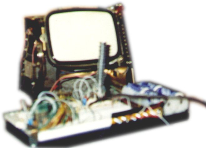
low frequency applications.Here is a picture of the scope I built when I was 15 years old. It was
a 9 inch portable black and white tv set. It was very limited, the beam
only deflected to the positive. That means only one half of ac
waveforms came through visible. The tall object partly obscuring the
screen is the deflection power transistor (there was only one.) The
preamp circuitry for deflection circuit was built on a Radio Shack
solderless breadboard. I used to hook this up to my stereo and watch
the dancing waveforms of the sound. This picture is the only one I had
of a homemade o-scope, but I’ve also converted several computer
monitors.
Warning!!! Please note!!! There are high voltages inside tv sets! Use
extreme caution! My advice is, never reach into the unit while it is
plugged in unless you are real sure of what you are doing! I accept no
liability whatsoever for the risks you take in following the plans
outlined below. Not all tv sets and computer monitors are alike, so
these plans are only exemplary of one way you might do this.
Inside the cabinet of a TV or computer monitor you will find at the
back of the picture tube, the yoke coil assembly. Once you locate it,
note the clamp that secures it to the picture tube. You will need to
loosen this clamp and rotate the coil 90 degrees, either clockwise or
counterclockwise, whichever direction makes the vertical sweep become a
left to right horizontal sweep.
 Step one, identifying the components
After this is done, you can retighten the clamp if you like, but keep
in mind that you may want to adjust this a bit more to make the beam
run in a straight line across the screen. Now the Vertical deflection
circuit is the Horizontal deflection circuit.
 Step two, rotating the yoke coil 90 degrees
Now you need to disconnect the old Horizontal deflection circuitry from
the yoke coil and possibly provide it with a “dummy” coil so that it
continues to operate. (Some systems require this for the high voltage
generator to operate.) After you build the new deflection circuit, you
will connect it to the yoke coil for what is now a Vertical deflection
axis.
 Step three, maintaining the original drive circuitry
This step is for the sync circuit. The scope needs to syncronize its
sweep with a rising or falling edge of the signal under test so that
the trace does’nt crawl or race across the screen.What you need
to do is locate the wire that served as the vertical sync. If you are
converting a TTL monochrome computer monitor like I did, then it’s
really easy to do this. On the circuit board there will likely be a
wire that comes in from the signal cable that is labeled “VSYNC.”
Locate this wire or its trace on the circuit board and attach a wire to
it so you can connect it to the new deflection circuit.
 Step four, locating the vertical sync circuit
Here is the schematic for the new deflection circuit. This schematic is
what most of you came to this site looking for. Here are the values of
the components: R1, R2 are 10k 1/4 watt, and R3 and the resistor at
INP- are 100k 1/4 watt resistors. R4 and R5 are flameproof, heatsink
mounted resistors that are rated 50 watts and they are 5 ohms each. Q1
and Q2 are TO-3 npn darlington transistors of the 2N6578 type. Any type
can be used here as long as its npn and can handle 15 amps and 120
watts or so. L1 is the yoke coil that was the horiz deflect but since
you rotated the coil it deflects vertical. Q3 is a small switching npn
transistor of the 2N2222 type, although many different ones could be
used here, too.Connect SYNC to the tv’s vsync circuitry. Use extreme caution locating this connection.
Caution!!! The connections inp+ and inp- are very sensitive. You will
have to change the values of r3 and the resistor on inp- to higher
values for higher voltages under test. This circuit is very basic; I
enhance it where necessary to provide the information I need from my
circuit under test. It could be enhanced with op amps and other
circuitry to make it both more accurate and user friendly. Good Luck!
I would like some feedback from those of you who build from these
plans. Also, let me know any more details you need. Thanks in advance.
 Step five, building the new horizontal drive circuit