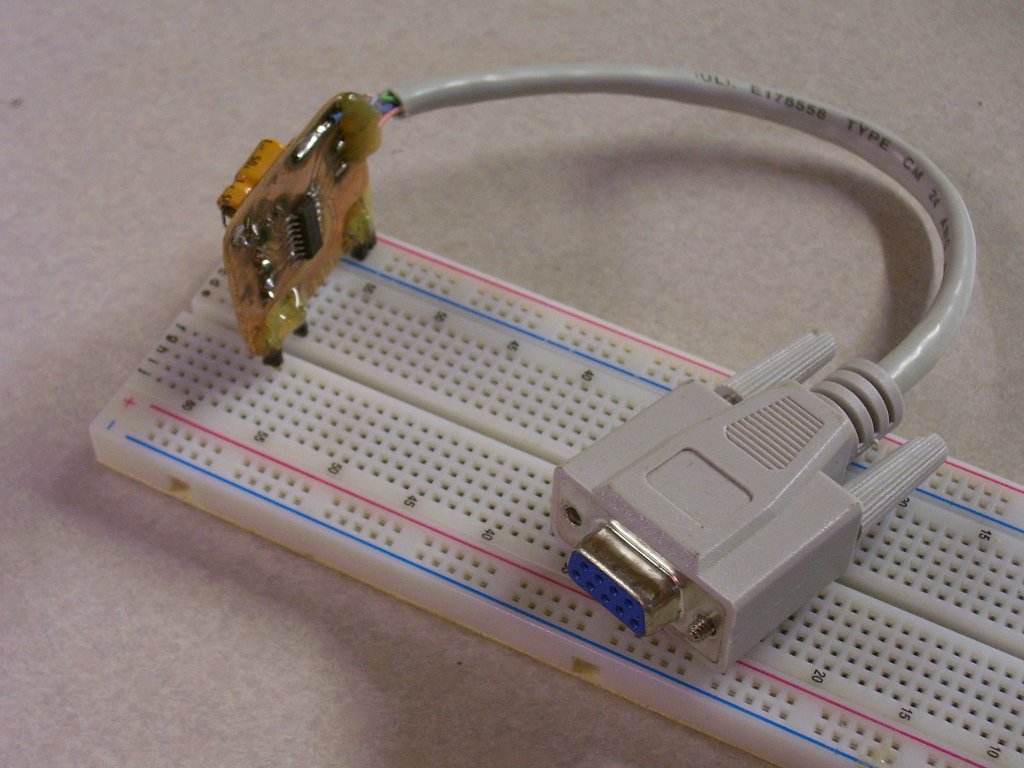
This is a followup to the article Breadboarding adapters . Recently I noticed a post on makezine about somebody that was making plug-in modules for solderless breadboarding, and thought I would share my creations as well. I also made a battery “juice bridge” a while before I noticed this. Great ideas.Pictured above is a little board with a MAX232 chip and necessary circuitry to power it from the rails of a breadboard, and the TX and RX pins breaking out into one row, upper and lower of the breadboard. If this circuit were made from a full-size DIP .10″ spacing version of the MAX232, it would take up 8 contact spaces on the board, just for the chip. The supporting parts would take up a bit more yet, and the wiring would be just plain messy. This plug-in module takes up a single row of contacts on the board.I made this originally to support my Atmel AVR breadboarding projects, to interface them directly to the serial port on my PC. This technique REALLY helps to organize such projects. In these cases, I’m not breadboarding the serial interface; it would just get wired up on the board and never change, just sit there and take up space on the board and present possibilities for wires or components to get dislodged. Instead, I made a handy module that eliminates many problems and is very fast to just plug in and go, no consulting schematics to re-invent the circuit on the breadboard every time a serial interface is needed.

Here’s another example. Two examples actually, at the left is a battery module that I made with a battery holder and cheap LED flashlight push-on-push-off switch to turn it on and off. In the center is a board that has a “manhattan-style” board, with an RC-car radio receiver glued to it. Power input and signal output is all broken out into pins that align to the spacing found on the common breadboards.This one differs a little from the serial module, it takes up two spaces on the board, for four connections. This could really run amok–revolutionizing breadboarding into somewhat of a “backplane” concept where traditional printed circuit (PCB) boarding and solderless breadboarding converge, with modules even running lengthwise on the board and using the 5-row contacts for “buses” in a manner of speaking.
 Another example. This LM311 circuit is the basis of many inductance meter circuits, and I used this one along with the MAX232 board as I was developing the code and circuitry for my inductance meter design.Again the circuit here, itself, has mostly an established schematic that doesn’t change much, except for the capacitor and inductor to be tested by the oscillator. So the two pins in the center are connections to the “variable” parts of the circuit, that are best served by the pluggability of the breadboard, while the fixed parts of the circuit are etched in copper on the module.