
Hot wire cutting bow, top terminal
Here are more details on my hot wire foam cutting table. I show the details of the terminals attaching the hot wire at top and bottom. The bow is made of threaded rod so adjusting an angle on the wire is trivial.
Here are more details on my hot wire foam cutting table. I show the
details of the terminals attaching the hot wire at top and bottom. The
bow is made of threaded rod so adjusting an angle on the wire is
trivial. Even though the rod is bent, the curve is shallow enough that the brass adjusting nuts still turn easily.The bow is bent to a 12-inch radius, which would make the rod (24 * pi) / 4, plus a few inches for mounting) approx 21 inches long.

Foam cutting table
The terminals are made from pieces of aluminum grounding bus bar, cut so that there are 2 holes per terminal. The knobs are tightened onto lengths of 1/4-28 threaded rod. The threads in the bus bar are 1/4-28 also, conveniently. To adjust the angle of the cut, the brass nuts are rotated to move down the length of the bow, which is made of 1/4-20 threaded rod.
Hot wire cutting bow,
top terminal
This is what I keep referring to as “bus bar”. It’s actually grounding bar that is used in electrical panels for grounding and neutral connections. It’s very handy stuff–you just cut to whatever length you need. The screws are 1/4-28 (fine thread), so it’s easy to substitute the set screws.

Aluminum grounding bar
for making terminals
Here the pattern is done except for the hole in the center for the
shaft. To cut the hole, I loosen the knob at lower right to release the
cutting wire. Then a reamer or punch is used to make a hole in the foam
pattern, the cutting wire is fed through this hole, and re-tightened.
The power is turned back on and the hole cut out. Then the wire is
again released and the plug is removed from the hole. The pattern is
ready to cast. Instead of making a core to form a hole in the casting,
I simply put a 5/8″ shaft through the hole and cast the metal right on
it. After cooling, the shaft is driven out. This forms a nice smooth
hole without ever machining it.

Pillow block template was
made using DeltaCAD
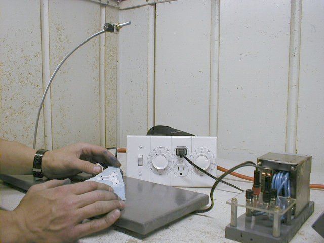
The base is a wooden board measuring 7 x 19 inches. Three rubber feet prevent rocking. The wires all connect on the bottom to help keep things organized.

Bottom view showing wires
The power wire to the bow fastens here. It could really fasten anywhere along the length of the bow, but the underside of the base is ideal to keep wires organized.

Wire attaching to bow
The bottom knob is also tightened onto a piece of 1/4-28 threaded rod, which goes through a hole drilled through the edge of the base to the center, to the bottom terminal.

Bottom knob at base
It took a longer drill bit than most, to drill the hole for the bottom terminal knob. Having the bottom wire able to be loosened quickly is a convenience feature, but it would really beg an explanation for any other way of tightening and releasing the bottom wire. I’m not sure how else I would have done it.

Bottom knob and terminal
The bottom terminal, showing the shaft from the terminal knob entering from the left. I ground the end of the tightening knob shafts round so they matched the roundness of the terminal hole. The power wire is “permanently” attached using the original set screw included with the bus bar. The yellow goop is 5-minute epoxy.

Bottom terminal closeup