Some time previous to getting my ham license, I was at a friends house who showed me an LC (inductance) meter built from a kit. It was based on a PIC16C22A, and I certainly do like the PIC mcu’s, but decided I would embark on the task of re-engineering my own that uses an Atmel AVR chip, the Atmega168. It’s been a journey. Also, I am giving away for free, the schematics, firmware, and source code as open source under the GPL. UPDATE: the source code is now hosted on github.com.
Inductance, Capacitance, LC Meter
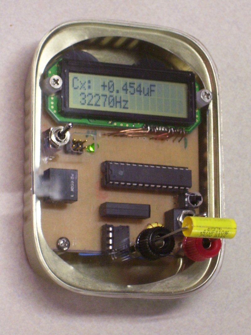
Pictured above is the first “prototype” LC meter, shown testing a .47uF capacitor. It’s reading a little bit low, but well within the +/- 10% rating of the cap. I still need to do some more precise calibration, but the meter is absolutely precise in terms of repeatability tests.
Another thing I need to do to improve the accuracy is to give it a more precisely regulated power source, typically a 7805 voltage regulator and a 9v battery, instead of running unregulated on the two 3v CR2032 batteries.
It seemed to run the CR2023′s down pretty fast, even though the circuit only draws around 25mA. Dropping the frequency down a bit should help–the crystals that were most convenient at the time were 16MHz which is overkill, it could probably run with the same precision at 4MHz.
I built the unit to fit inside an oyster can with a plexiglass cover, since I have begun eating
oysters and have those nice rounded cans lying about. This effort resulted in a very compact unit.
This LC meter has one feature that I haven’t seen on any others (to date), it shows the frequency that the test oscillator is running at.
This is important to consider, as many inductors (and probably capacitors) change slightly in value at different frequencies, and it’s important to consider the frequency when making a measurement.

Schematic screenshot from Eagle PCB designer
Here is the schematic. Click for a full size view. This was sketched in Eagle 5.7.0 from CadSoft Online. I am not ready to release the Eagle project file yet, so please don’t ask. This project is very much in beta yet, and I built the prototype pictured above on some home made “protoboard” so I don’t yet have a PCB trace pattern available yet either.
This schematic is not quite accurate to the pictured prototype, because it shows the MAX232 chip, which I did not include on-board, but implemented on a separate board for a debugging interface to my pc serial port.
You may also download the source code and hex file, and use them any way you like including commercial use, within the limits of the GPL open-source license .
Source code, project files including .hex file, lc_meter.zip
I used AVR Studio 4 as my development IDE, and PonyProg to upload the hex file to the mcu.
I wrote the firmware in C and used the AVR GCC and C libraries WinAVR (avr-libc) and Procyon Engineering’s AVRlib in the development of the binary hex file for the LC Meter, which are also GPL’d.
 Here are pictures of the front and back of the board.
The black object on the mid-lower left is a 1/8″ stereo headphone jack that serves to break out the UART serial interface of the AVR chip. I used the serial interface for a lot of debugging during development, and hope to keep it for advanced features (such as calibration) as well.

The design also includes the 6-pin ICSP header, to make it easy to upload new firmwares.
Note that the unit is pictured here with the Atmega8, but later I switched to the Atmega168, and the source code is compiled for the Atmega168, and the test shot above is shown running with the Atmega168.
The reason for this is the Atmega8 did not have enough memory to hold all the code for the LCD driver (HD44780 compatible) and the serial driver etc.
I also had to considerably modify Procyon’s AVRlib file, lcd.c to utilize the lower 4 bits of Port C rather than the upper, as I needed to use Port C and the Atmega8 does not bring out all of the I/O from Port C, only the lower 7 bits.
The yellow inductor is a T37-6, the best I can tell. It came out of a compact flourescent light bulb board. It took only nine turns to achieve the 68uH needed for stable oscillation.
Front of the LC Meter main board
This circuit uses the very popular LM311 oscillator circuit that many of the other build-yourself LC meters use. I soldered all 5 of the surface mount resistors within the footprint of the LM311′s 8-pin DIP socket, a very compact and stable design. The main capacitor and inductor are not far away either.
The 16MHz crystal was originally mounted in through-hole fashion, and I moved it, thinking that it was affecting the stability of the LC oscillator circuit (which it was not) and so it could be moved back to the front of the board.
As I mentioned earlier, this is in beta stages and I have many improvements to make including a PCB trace, so please be patient.
Click on any of the pictures on this page for a larger view.